camera
Here we want to describe the camera we built and which formed the basis for the toolkits stitching capabilities. Consider this description a suggestion.There are many different ways to create panoramic image and video, all of which differ in their solution to cover a wider vision space, and of course there are quite a couple of commercial solutions for wide panoramic imaging available. While most of the commercial solutions are quite expensive, we wanted to create any accessible tool, that is cheap and quite easy to build, so that many people can experiment with panoramic video. Again, keep in mind, that the goal was to create a camera that is able to handle panoramic video, live, and not only panoramic photos(which can be taken by a vast number of mobile phones nowadays :) )In the end we chose normal
off-the-shelf webcams to
build the camera. The sony ps3eye camera has proven to be a good
choice, since it combines high framerates and has a good image-quality
with a reasonable low price. The upside is, that there are drivers for
this camera available for every OS, or are natively supported in the
case of Linux. On the downside there are problems with Windows and OSX
when it comes to handling multiple USB-devices simultaneously. On
Windows there is a special driver from codelaboratories
available, that enables the system to handle more than one ps3eye, on
OSX we did not find a solution to this particular problem. Again: this
is not a problem when using Linux, where every camera registers as a
separate video-device.
Another solution to this particular problem would be using Firewire-based cameras, which can be daisy-chained and are reported to work as mutliples on OSX.(those cameras are more expensove, though)
Due to the maximum bandwidth of the USB2 standard it could also be a
problem, that only 2 cameras can be used on one USB2 CONTROLLER, which
rules out most of the notebooks, at least if one wants to use more then
2 cameras.
constructionAnother solution to this particular problem would be using Firewire-based cameras, which can be daisy-chained and are reported to work as mutliples on OSX.(those cameras are more expensove, though)
 |
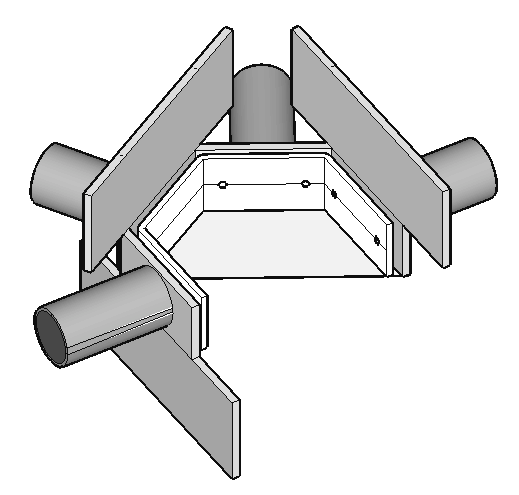 |
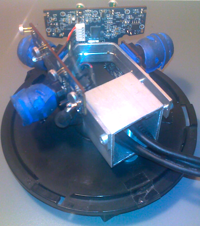
The reason to note the problems with multiple-cameras being used on one computer lies in the construction of the camera: We chose to arrange multiple ps3eye cameras horicontally on a circle, each angled to its neighboring camera by a certain amount, so that a angle of vision of about 230 degree can be achieved.
One major goal in the construction of the camera should be to find an way to align the cameras permanently, so that one does not have to re-adjust the stitching paramters in the software again and again. To achieve this, we mounted the cameras on a standard aluminium profile.
The profiles bending angle and the angles of the cameras towards each other were determined by experiment. To get this angles, a certain issues have to be taken into account in order to get good results from the camera:
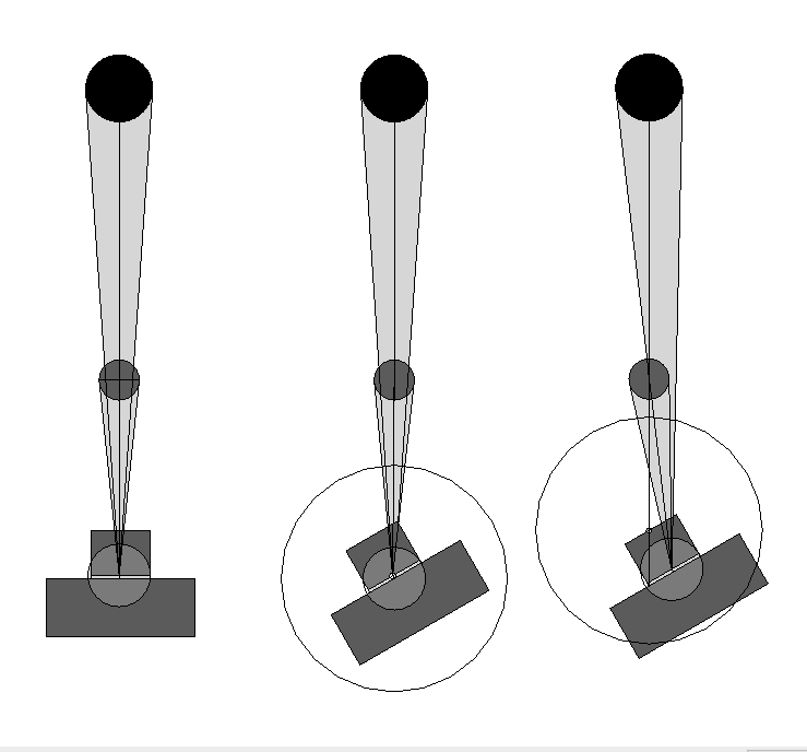
Parallax errors
Parallax error
describes the relative change in the position of an observed object
introduced through the shift of the observer. If a camera is rotated
around its optical center, images can be stitched together quite easy,
since they have similar projective properties. The picture on the left
below tries to illustrate the problem of camera rotation around the
camera centre (in the middle) and off-centre rotation (on the right).
It can be seen, that the two objects are still in line when the camera
is rotated around its centre. The parallax effect is most obvious for
objects close to the observer, but has far less impact on objects
farther away. This problem is of great importance for panoramic video
and image creation, since we rely on sources that overlap in a portion
of its visual information, where the images can be stitched together.
Now, if a couple of cameras are setup on a circle horizontally, it is nearly impossible to align the rotational axis on the camera centre due to their construction size.
To reduce the impact of the parallax on the final image material and keep the construction, a little trick has to be applied:
If one reduces the overlap between the single camera modules to a minimum, the resulting image- sources would still share a portion of information with each other, marked with “A” in the right picture below, exactly this portion, where ideally the parallax has much less effect: the information in the distance. Objects that are closer and in between the optic field of two camera modules (B in right picture below) simply are not shown at all, much like a blind spot of a car side mirror.
This leads towards a tradeoff: the smaller the overlap is, the better
the stitching works, but the farther the observed scenery has to be
away to record continuous movements along the whole visual field of the
camera array.
Through experimentation we found out, that, with an angle of 60 degrees between the camera modules2, a minimum distance of 2 to 3 meters for the observed scenery shows acceptable results, given that the radius of the circle, the modules are arranged on is as small as possible.
For more detailed information on the construction, feel free to contact us.
Now, if a couple of cameras are setup on a circle horizontally, it is nearly impossible to align the rotational axis on the camera centre due to their construction size.
To reduce the impact of the parallax on the final image material and keep the construction, a little trick has to be applied:
If one reduces the overlap between the single camera modules to a minimum, the resulting image- sources would still share a portion of information with each other, marked with “A” in the right picture below, exactly this portion, where ideally the parallax has much less effect: the information in the distance. Objects that are closer and in between the optic field of two camera modules (B in right picture below) simply are not shown at all, much like a blind spot of a car side mirror.
 |
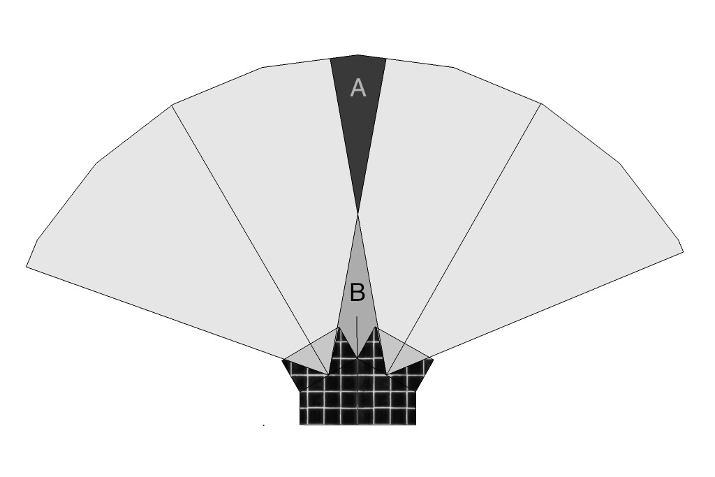 |
Through experimentation we found out, that, with an angle of 60 degrees between the camera modules2, a minimum distance of 2 to 3 meters for the observed scenery shows acceptable results, given that the radius of the circle, the modules are arranged on is as small as possible.
For more detailed information on the construction, feel free to contact us.